An unserviceable CFL, the filament has reached the end of its life but
there is every possibility that the electronic ballast circuit inside
the bottom of the CFL is in working condition. The night lamp circuit
described here uses the serviceable electronic circuit fitted in the
base of an 11-watt CFL
there is every possibility that the electronic ballast circuit inside
the bottom of the CFL is in working condition. The night lamp circuit
described here uses the serviceable electronic circuit fitted in the
base of an 11-watt CFL
For constructing this night lamp, remove the CFL glass tube and replace it
with four white LEDs as described below. You should be careful not to
break the tube as it contains hazardous materials such as mercury.
Carefully open the base of CFL holder using an appropriate tool. You can
see the electronic ballast circuit on a circular PCB
with four white LEDs as described below. You should be careful not to
break the tube as it contains hazardous materials such as mercury.
Carefully open the base of CFL holder using an appropriate tool. You can
see the electronic ballast circuit on a circular PCB
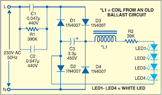
Use the components from the ballast circuit and a series combination of
four bright white LEDs as shown in Fig. 1. Remove all other components
from the original ballast circuit. As per the requirement of light
intensity in your room, you can increase the number of white LEDs up to
eight. As shown in Figure, the full-wave bridge rectifier
comprising diodes D1 through D4 converts AC voltage into DC voltage.
Snubber capacitor C1 at the input reduces the line input voltage of 230V
to a very low-level AC voltage. Series current-limiting resistor R2 and
series inductor coil L1 avoid voltage spikes. Fit the circular
PCB in the waste CFL holder and your night lamp is ready for use.

